... or FreeCAD to the real world without 3d printing, but a 3 meters CNC mill:
Updated ( because we won!! :D )
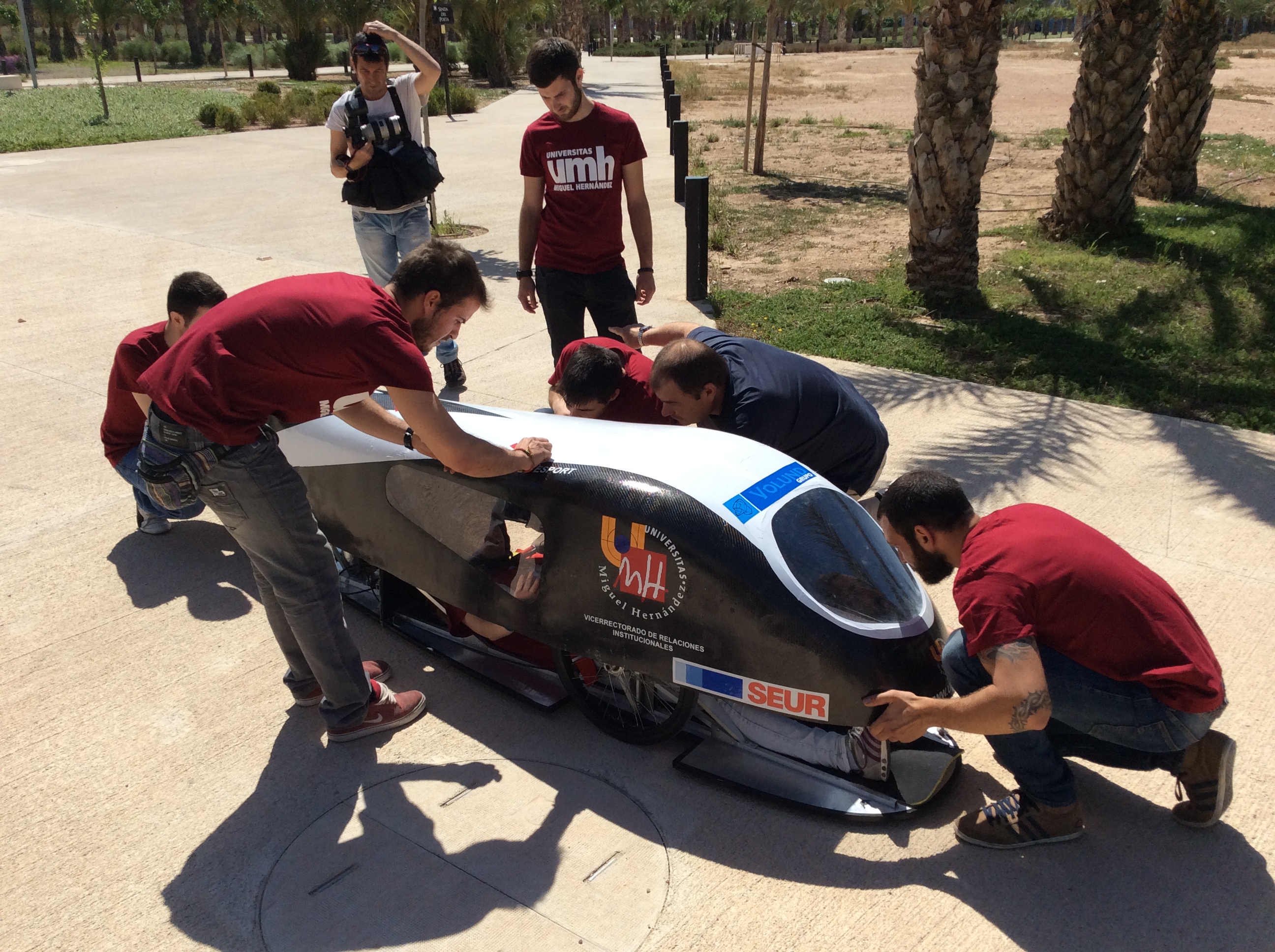
Prototype Dátil 15 wins the European SEM on Ethanol
UPDATED:
The result:
On the news
The story:
I am member of the UMH Team, a group of students that build a prototype car to race at the Shell Ecomarathon, an event that this year takes place at Rotterdam. Currently, we are in the first position of the spanish championship, leading it in the combustion category, with a fuel consumption of 1223 kilometers / litre of ethanol. In the European competition, we have been at the top ten, but past edition we finished 13th at combustion category and 3rd on ethanol.This year we are building a completely new car that we hope bring us to the podium.
What I am showing here is the cover of the new prototype, that I designed using FreeCAD, simulated using SolidWorks, and later converted to CNC code using Hypermill. Special thanks go to Volund Group for their help and support.
The FreeCAD part:
The cover is designed using already existing tools, basically is a loft going through several sketches that I placed using a simple script.This is the first one I did, just to test if FreeCAD was able to acomplish this work.
The car frame was made with Autodesk Inventor and imported as IGES, then I started to create the sketch-ribs and finally a loft through all them. I adjusted the sketches to obtain the desired shape. Once happy with it, I made the windows and a basic visibility test to ensure we are compliance with the rules of the race.
The rules specify that a pilot must be able to see a polar array of cylinders that are around the car with an angle of 30 degrees between each one.
Thanks to FreeCADs perspective view, I could check window sizes and do some optimization.
This is the pilot's point of view
Simulation:
The covering was simulated using SolidWorks, resulting in a Cx of 0.33.Milling:
Once we performed another tests and confirmed that everything was ready, we started to machine a foam block to create a positive mould. We have used a medium-sized CNC milling center (Volund Group) that can handle the 3000 mm of length of this car:
Raw block:
Rough pass:
Smoothing pass:

The smoothing pass is finishing as I write this. What we are doing next is to epoxy and fiberglass it to create the negative mould and then, do the carboon fiber cover. I will edit this post to upload finished pictures.
I hope this serves an example of real world usage of FreeCAD, beyond 3D printing.
Maybe I do a tutorial to show how to model surfaces like this prototype cover, stay tuned.
Bye!


Thanks for posting this. It's great seeing real world designs completed, using FreeCAD. I like your blog and read it frequently.
ReplyDeleteI'm glad you like it, thanks for your support!
ReplyDeleteThis comment has been removed by the author.
ReplyDeleteHi,
ReplyDeletethis topic is very interesting.
What CAD/CAM tool did you use? Or differently asked: How did you obtain G-Code/machine instructions from the FreeCAD model?
Good luck for the competition!
Thanks Köbes!
ReplyDeleteThe software used to generate the G-Code was a very old version (2002) of "Mechanical Desktop" (seems like some sort of AutoCAD with a module called Hypermill for CNC machines) The model was exported from FreeCAD as a STEP file and both programs worked flawlessly.