Sunday, 14 December 2014

FreeCAD: Sheet metal idea part 2

UPDATE 2:  Document structure and basic tools
-
UPDATE: Ulrich has developed an unfolding algorithm that can be used as a macro.
-

Some things have changed since sheet metal part 1, where, for example, faces were classified by being flat or cylindrical, or folds only counted if their angle was 90º.

Even thought the algorithm is not finished (current problem is being discussed here), the new approach I'm going to explain here is more robust and is not even limited to face geometry or fold angles. You can even do folds with different radius, this face classifier can withstand it.

This is the part I'm going to use as example:


It has been created using this script, and you can download it here.

The workflow that I have in mind to unfold a part is:

- Select the face that will behave as base (all faces will be unfolded over the plane by it described )
- Run the script.

Let's start.

Import the libraries:

As always, we need to import some library. The only one we need is "Gui", from the  main FreeCAD library. In addition, we set the thickness of the sheet:

from FreeCAD import Gui
thk = 1.0

Retrieve user selection:

This is a basic command very useful at writing macros:

# Get Selected Shape and Face
SelObject = Gui.Selection.getSelection()[0].Shape
SelFace = Gui.Selection.getSelectionEx()[0].SubObjects[0]

SelObjects contains the selected shape and SelFace contains the selected face. Note that user only needs to click on the face and with that we can take the whole object.

Get ride off non useful faces:

The action starts here, but first: Which are the non-useful faces?
They are the ones marked in green at the picture:


This faces are not needed because they do not store useful geometry data. To clear things in a future, we are going to create a list excluding this faces:

faceList = [] # Create an empty list that will hold the filtered faces
for face in SelObject.Faces:
  apnd = True
  for edge in face.Edges: # Measure length of all edges from all faces
    if abs( edge.Length - thk ) < 0.001: #tolerance because float point things
      apnd = False # If edge length is equal to thickness, do not append it.
      break
  
  if apnd:  # If the face hasn't any edge with length == thickness, append it.
    faceList.append( face )


Did it work? Is something easy to test: select a face from the object and paste at FreeCAD's python console all the code.
Then, do:

len( SelObject.Faces )

len( faceList )


The first one gives "46" and the second "18". That's a great data reduction!

Unfold tree: step 1

We have a list containing only meaningful data, but this data is duplicated. Why? 


Is duplicated because the faces selected in the first picture (back of the part) are parallel to the faces on the second picture (top of the part). While is easy to create another filter to remove the repeated faces, is very hard to not lose the connection between faces with it.

So we are going to create a list containing wich face links to wich face or group of faces. This list has this form:

    index       A        B        C        D        E        F
     "list" =  [ [B],[A,C,D],[B],  [B,E,F], [D],    [D] ]

The index number belongs to the position in "faceList" of the face. The content under the index are the faces linked to that face.
To explain it better, "list" is the solution to faces links of this simplified part:


So how we create a list like that one?
Just run this little "monster":

# auxiliar function: find face number (index) in faceList:
def gfN( inFace ):
  SF_COM = inFace.CenterOfMass
  SF_NOR = inFace.normalAt( 0, 0 )
  for n in range( len( faceList ) ):
    F_COM = faceList[n].CenterOfMass
    F_NOR = faceList[n].normalAt(0,0)
    if SF_COM == F_COM and SF_NOR == F_NOR:
      break

  return n

# get selected face position (index)  in faceList:
SelFaceNumber = gfN( SelFace )

# auxiliar function: get faces linked to input face (returns position in faceList )
def gfR( inFaceN ):
  temporalList0 = []
  inFace = faceList[inFaceN]
  for inEdge in inFace.Edges:
    if str( inEdge.Curve )[1:5] == "Line":
      P_ia = inEdge.valueAt( 0.0 )
      P_ib = inEdge.valueAt( inEdge.Length )
      V_0 = ( P_ib - P_ia )
      for n in range( len( faceList ) ):
        if n != inFaceN:
          face = faceList[n]
          for edge in face.Edges:
            P_a = edge.valueAt( 0.0 )
            P_b = edge.valueAt( edge.Length )
            V1 = P_b - P_ib
            V2 = P_a - P_ia
            condition0 = abs( ( V_0.cross( V1 ) ).Length ) < 0.0001
            condition1 = abs( ( V_0.cross( V2 ) ).Length ) < 0.0001
            if condition0 and condition1:
              faceNumber = gfN( face )
              temporalList0.append( faceNumber )
              break

  # clean from repeated faces
  temporalList1 = []
  for i in temporalList0:
    if not( i in temporalList1 ):
      temporalList1.append( i )

  return temporalList1


compFaceRel = []
for fn in range( len( faceList ) ):
  data = gfR( fn )
  compFaceRel.append( data )


If you run the code above, and then type "comFaceRel" you should see something like:

[[3, 2], [4, 5], [0, 3, 6], [0, 7], [1, 8], [1, 4, 9], [2], [3, 10, 11], [4], [5, 12, 13], [7, 14], [7, 10, 15], [9, 13, 16], [9, 17], [10], [11], [12], [13]]

How a link is recognized:
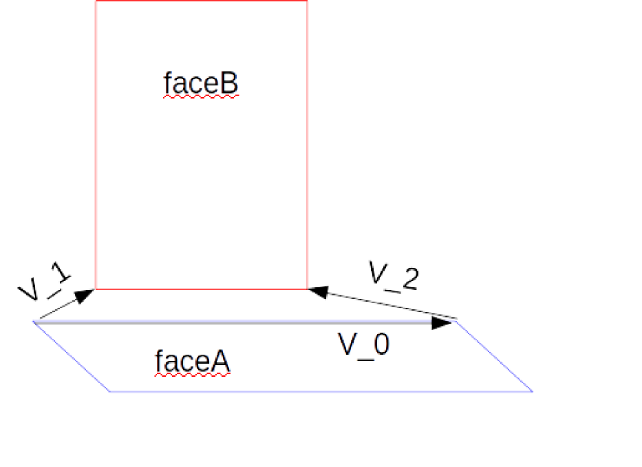


faceA is the current face being analyzed to inspect its links. FaceB is one of all the faces contained in facesList suspicious of being linked with faceA. 
V_0 the director vector of the current edge of faceA being inspected. V1 and V2 are vectors going from the end-points of the edge from faceA to the end-points of an edge owned by faceB. 
A face is linked if the cross products V1xV0 and V2xV0 have a length of 0.

All this is calculated inside the previous function "gfR".


At the moment, this is the current state of the sheet metal workbench. Next step is to get the link between final nodes of the tree of faces to the selected face to unfold. 
Taking the previous example model with faces A, B, C..., the needed list previous to unfold is, with B as unfold base:
                                                  [ [A,B], [C,D], [F,D,B], [E,D,B]]

Knowing that list would be the major step forward. With it, the unfold algorithm would be almost finished.


Complete code:

# JMG december 2014
from FreeCAD import Gui

thk = 1.0

# Get Selected Shape and Face
SelObject = Gui.Selection.getSelection()[0].Shape
SelFace = Gui.Selection.getSelectionEx()[0].SubObjects[0]

# remove faces placed on the thickness
faceList = [] # Create an empty list that will hold the filtered faces
for face in SelObject.Faces:
  apnd = True
  for edge in face.Edges: # Measure length of all edges from all faces
    if abs( edge.Length - thk ) < 0.001: #tolerance because float point things
      apnd = False # If edge length is equal to thickness, do not append it.
      break
  
  if apnd:  # If the face hasn't any edge with length == thickness, append it.
    faceList.append( face )


# auxiliar function: find face number (index) in faceList:
def gfN( inFace ):
  SF_COM = inFace.CenterOfMass
  SF_NOR = inFace.normalAt( 0, 0 )
  for n in range( len( faceList ) ):
    F_COM = faceList[n].CenterOfMass
    F_NOR = faceList[n].normalAt(0,0)
    if SF_COM == F_COM and SF_NOR == F_NOR:
      break

  return n

# get selected face position (index)  in faceList:
SelFaceNumber = gfN( SelFace )

# auxiliar function: get faces linked to input face (returns position in faceList )
def gfR( inFaceN ):
  temporalList0 = []
  inFace = faceList[inFaceN]
  for inEdge in inFace.Edges:
    if str( inEdge.Curve )[1:5] == "Line":
      P_ia = inEdge.valueAt( 0.0 )
      P_ib = inEdge.valueAt( inEdge.Length )
      V_0 = ( P_ib - P_ia )
      for n in range( len( faceList ) ):
        if n != inFaceN:
          face = faceList[n]
          for edge in face.Edges:
            P_a = edge.valueAt( 0.0 )
            P_b = edge.valueAt( edge.Length )
            V1 = P_b - P_ib
            V2 = P_a - P_ia
            condition0 = abs( ( V_0.cross( V1 ) ).Length ) < 0.0001
            condition1 = abs( ( V_0.cross( V2 ) ).Length ) < 0.0001
            if condition0 and condition1:
              faceNumber = gfN( face )
              temporalList0.append( faceNumber )
              break

  # clean from repeated faces
  temporalList1 = []
  for i in temporalList0:
    if not( i in temporalList1 ):
      temporalList1.append( i )

  return temporalList1


compFaceRel = []
for fn in range( len( faceList ) ):
  data = gfR( fn )
  compFaceRel.append( data )


Bye!

Thursday, 11 December 2014

FreeCAD: Sheet metal tool "Add Wall"

 Thought not seen here, I work in the sheet metal workbench from time to time (last update), being my greater effort coding the unfold algorithm (related post). But I also work at the surrounding tools that this workbench needs, one of them is almost usable and is the reason of this post.

Add wall tool:


When I create the "dummy" shapes for testing the unfolding algorithm, the process is somewhat tedious. So I created this tool and developed it a bit to be easily integrated in the workbench in a future.

The utility of the tool is explained with this video:


Code can be found here

How to use it:

The script contains the function  "addWall", when calling it this are the possible input parameters:

thk = float:           Sheet thickness, 1.0 is the default value
bendR =  float:     Bend radius, default value is 3.0
alpha = float:       Angle of the new wall plane in reference to previous shape plane. 0 will give error (infinite bending radius needed ). By default 90º

L1 and L2 are better explained with a picture:


L1 and L2 values (float) modify the lengths noted by the white dimension marks. By default 0.0

Relief = boolean:  Create or not square relief slots (I think this is the correct name, but tell me if not) like this:


Relief slots have two parameters:

rlfWidth = float: The width of the relief, by default 0.5
rlfDepth = float: The depth of the relif, by default 1.0

Other parameters are:

inverted = boolean: Reverse bend direction, false by default
create = boolean:  This is to merge new wall with current object, true by default. Workbench utility
sketch = boolean: Automatically places a new sketch on new wall, false by default.


To use it, copy-paste the code at FreeCAD's  python console, select one suitable face to place a new wall and then type "addWall( arguments )".

It should work.


Bye!

Friday, 14 November 2014

FreeCAD: Tour camera

Imagine that you draw a house or a building in FreeCAD with all its details and interior elements. Wouldn't it be awesome if you could get into just like if you were walking inside?
This "tour camera" macro makes it possible.


This is the small "town" I've created for testing this macro. Download it here, get the full macro
code at the bottom of the post, and follow this microtutorial


(notice the camera track in orange)

How does it work?

Very simple, create a sketch over the surface you want to travel and exit. Then, switch view mode to "perspective view", and finally,  at the previous sketch, select one line and paste this at the python console:

from pivy import coin
import time
from FreeCAD import Base
cam = FreeCADGui.ActiveDocument.ActiveView.getCameraNode()
trajectory = Gui.Selection.getSelectionEx()[0].Object.Shape.Edges
for edge in trajectory:
  startPoint = edge.valueAt( 0.0 )
  endPoint = edge.valueAt( edge.Length )
  dirVector = ( endPoint - startPoint ).normalize()
  currentPoint = startPoint
  while (currentPoint - startPoint).Length < edge.Length:
    currentPoint = currentPoint + dirVector
    cam.position.setValue(currentPoint + Base.Vector( 0,0, 10) )
    cam.pointAt( coin.SbVec3f( endPoint[0], endPoint[1], endPoint[2]+10) , coin.SbVec3f( 0, 0, 1 ) )
    Gui.updateGui()
    time.sleep(0.005)

What it does is:

-Gets camera node and sketch track as a list of edges
-Iterates over the list of edges, positioning the camera from edge start to the edge length position, looking at the edge endpoint.

If you did the above, you should be travelling like this:


But is not only your screen the one that shakes badly when you go from one line to the next, mine too.
When camera jumps from one line to the next, it is orientated to the new endpoint in one step. That's the origin of the shaking behavior.

So, with a bit more of complication, I've improved this (new "town" included :):


In this version, camera walks along the actual edge pointing its view to a vector, with a given length and the same direction than the movement. Once this vector reaches the intersection with the next line, the camera rotates to align with the end point of that line. 
In conclusion, you get a smooth transition and a nice walk around.

But that's the behavior roughly speaking, for the real thing, please look the code below.

# JMG November 2014
from pivy import coin
import time
from FreeCAD import Base
camera = FreeCADGui.ActiveDocument.ActiveView.getCameraNode()
trajectory = Gui.Selection.getSelectionEx()[0].Object.Shape.Edges
camHeight = 10   # Height of the camera above the track
lookVectorLength = 80   # Distance from next line start where the camera starts to align with new direction
for i in range( len( trajectory ) - 1):
  currEdge = trajectory[i]
  currEdgeDir = ( currEdge.valueAt( currEdge.Length ) - currEdge.valueAt( 0.0 ) ).normalize()
  nextEdge = trajectory[i+1]
  nextEdgeDir = ( nextEdge.valueAt( nextEdge.Length ) - nextEdge.valueAt( 0.0 ) ).normalize()
  currPos = currEdge.valueAt( 0.0 )
  while (currPos - currEdge.valueAt( 0.0 ) ).Length < currEdge.Length:
    currPos = currPos + currEdgeDir
    camera.position.setValue( currPos  + Base.Vector( 0, 0, camHeight ) )
    cameraLookVector = currEdgeDir*lookVectorLength
    if (cameraLookVector + currPos - currEdge.valueAt(0.0) ).Length > currEdge.Length:
      L = ( cameraLookVector + ( currPos - currEdge.valueAt( 0.0 ) ) ).Length - currEdge.Length
      lookVector = nextEdgeDir*L + nextEdge.valueAt( 0.0 )
      
    else:
      lookVector = currEdge.valueAt( currEdge.Length )
    
    camera.pointAt( coin.SbVec3f( lookVector[0], lookVector[1], lookVector[2] + camHeight ), coin.SbVec3f( 0, 0, 1 ) )
    Gui.updateGui()
    time.sleep( 0.004 )


It features two configurable parameters:

- camHeight: height of the camera above the track ( over z axis )

-lookVectorLength: distance from the endpoint of the current line at witch the camera starts to rotate to align with the next line. Try values, the more it approaches to 0, the more shake you get. But too big values will shake too!

Before leaving, a funny thing: instead of the sketch track, select the 3d model and paste the code.

Code update:

A complex track may involve booleans, and , as every time you operate with a shape their subelements get reorganized, the result is something like what .rpv got trying to tour inside a 3d printer. Curious as a background video in presentations, but not the expected behavior.

The solution is to rearrange the list of edges so next edge start begins at the current edge end. It is achieved this way:

SelectedEdge = Gui.Selection.getSelectionEx()[0].SubObjects[0]
RawTrajectory = Gui.Selection.getSelectionEx()[0].Object.Shape.Edges

# Edge rearrangement inside trajectory list
trajectory = []
trajectory.append( SelectedEdge )
currentEdge = SelectedEdge
for n in range( len( RawTrajectory ) ):
  for edge in RawTrajectory:
    if edge.valueAt(0.0) == currentEdge.valueAt( currentEdge.Length ):
      trajectory.append( edge )
      currentEdge = edge
      break


Full code:

Complete version featuring everything:

# JMG November 2014
from pivy import coin
import time
from FreeCAD import Base
camera = FreeCADGui.ActiveDocument.ActiveView.getCameraNode()
SelectedEdge = Gui.Selection.getSelectionEx()[0].SubObjects[0]
RawTrajectory = Gui.Selection.getSelectionEx()[0].Object.Shape.Edges

# Edge rearrangement inside trajectory list
trajectory = []
trajectory.append( SelectedEdge )
currentEdge = SelectedEdge
for n in range( len( RawTrajectory ) ):
  for edge in RawTrajectory:
    if edge.valueAt(0.0) == currentEdge.valueAt( currentEdge.Length ):
      trajectory.append( edge )
      currentEdge = edge
      break

camHeight = 10   # Height of the camera above the track
lookVectorLength = 80   # Distance from next line start where the camera starts to align with new direction
for i in range( len( trajectory ) - 1):
  currEdge = trajectory[i]
  currEdgeDir = ( currEdge.valueAt( currEdge.Length ) - currEdge.valueAt( 0.0 ) ).normalize()
  nextEdge = trajectory[i+1]
  nextEdgeDir = ( nextEdge.valueAt( nextEdge.Length ) - nextEdge.valueAt( 0.0 ) ).normalize()
  currPos = currEdge.valueAt( 0.0 )
  while (currPos - currEdge.valueAt( 0.0 ) ).Length < currEdge.Length:
    currPos = currPos + currEdgeDir
    camera.position.setValue( currPos  + Base.Vector( 0, 0, camHeight ) )
    cameraLookVector = currEdgeDir*lookVectorLength
    if (cameraLookVector + currPos - currEdge.valueAt(0.0) ).Length > currEdge.Length:
      L = ( cameraLookVector + ( currPos - currEdge.valueAt( 0.0 ) ) ).Length - currEdge.Length
      lookVector = nextEdgeDir*L + nextEdge.valueAt( 0.0 )
      
    else:
      lookVector = currEdge.valueAt( currEdge.Length )
    
    camera.pointAt( coin.SbVec3f( lookVector[0], lookVector[1], lookVector[2] + camHeight ), coin.SbVec3f( 0, 0, 1 ) )
    Gui.updateGui()
    time.sleep( 0.004 )


Enjoy!