The input is an int array { MA, MB, MC, MD } where each int means the number of steps (positive or negative).
The stepper movement logic is stored into a boolean[8] array { SA, DA, SB, DB.... } where SA means step for motor A and DA is the direction bit of the motor A (for a 2 wire stepper driver, like the a4988). This array is erased and re-computed every loop cycle with the next movement, so real motor stepping has to take place inside this loop.
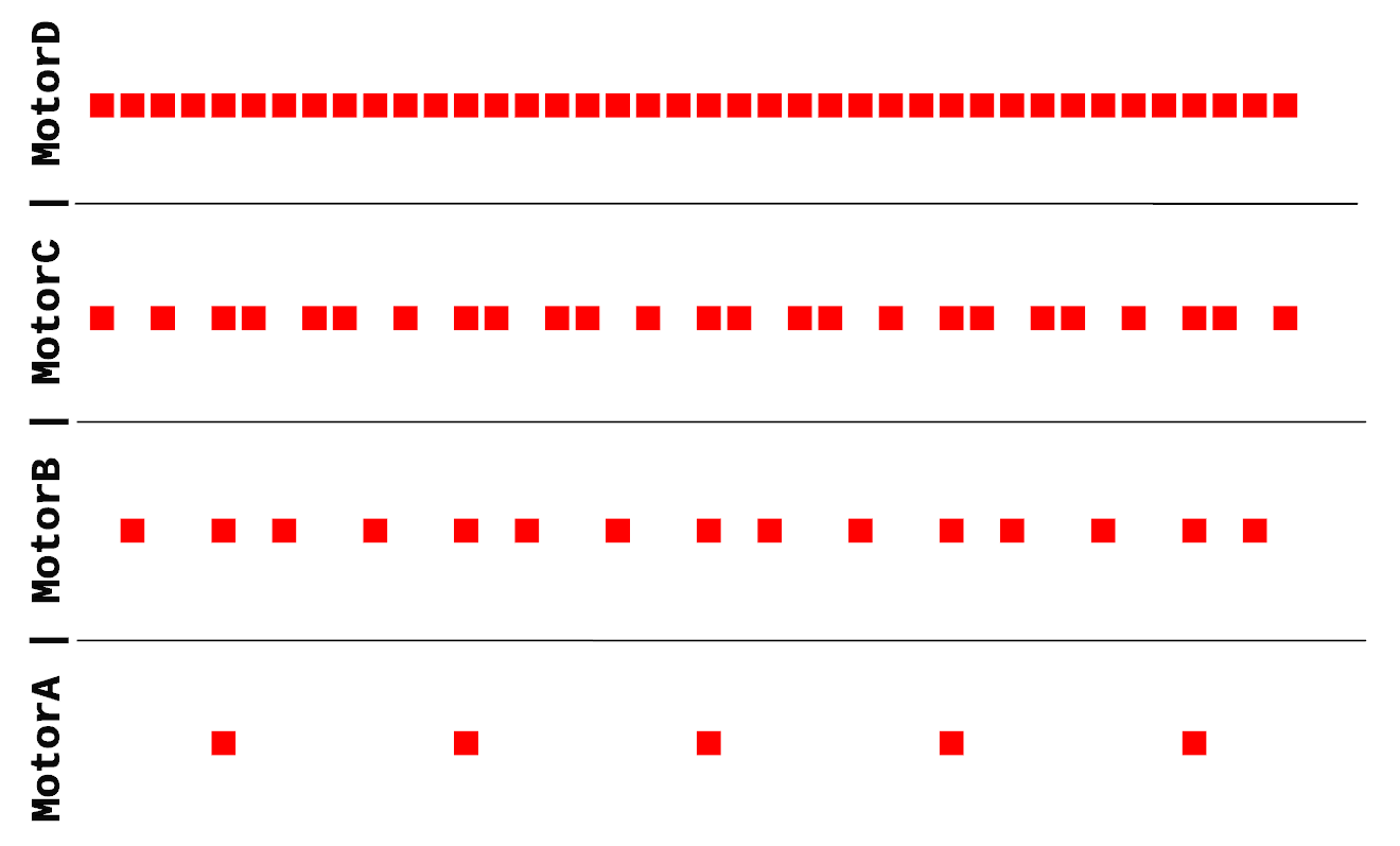
The image below (created with FreeCAD) shows a representation of the algorithm output for a requested movement of ( 5, 15, 25, 40 ) steps.
Input ( 5, 15, 25, 40 ), step bit only
It would be possible to do some kind of buffer by translating that boolean array into an int inside an int array. This should be a more-less memory efficient way of decoupling motion logic and motion execution, something to try in a future.
The code:
/*
* JMG October 2015
* NiCr Stepper Sync Algorithm V1
* Tested on Arduino Nano (Ide 1:635)
*
*/// stepper_instruction { Step1A, Dir1A, Step1B, Dir1B, Step2A, Dir2A, Step2B, Dir2B }bool stepper_instruction[8] = { 0, 0, 0, 0, 0, 0, 0, 0 };
voidmoveAB( int Adx, int Ady, int Bdx, int Bdy )
{
int delta[4] = { Adx, Ady, Bdx, Bdy };
int aux = 0;
for( int i = 0; i < 4; i++ )
{
if( abs(delta[i]) > aux )
{
aux = abs(delta[i]);
}
}
float R[4] = { 0, 0, 0, 0 };
for( int i = 0; i < 4; i++ )
{
R[i] = (float)delta[i] / (float)aux;
}
int inc[4] = { 0, 0, 0, 0 };
int acc[4] = { 0, 0, 0, 0 };
int j = 0;
while( ( acc[0] != Adx )||( acc[1] != Ady )||( acc[2] != Bdx )||( acc[3] != Bdy ) )
{
j++;
for( int i = 0; i < 4; i++ )
{
inc[i] = round( R[i]*j - acc[i] );
acc[i] = acc[i] + inc[i];
stepper_instruction[2*i] = abs( inc[i] );
if( inc[i] < 0 ) { stepper_instruction[2*i+1] = 1; }
else { stepper_instruction[2*i+1] = 0; }
}
for( int i = 0; i < 7; i++ )
{
Serial.print( stepper_instruction[i] );
}
Serial.println( stepper_instruction[7] );
for( int i = 0; i < 8; i++ )
{
stepper_instruction[i] = 0;
}
}
for( int i = 0; i < 4; i++ )
{
Serial.print( acc[i] );
}
Serial.println();
for( int i = 0; i < 4; i++ )
{
Serial.print( delta[i] );
}
}
voidsetup()
{
Serial.begin( 115200 );
delay( 500 );
moveAB( 100, -5000, 780, 25 );
}
voidloop()
{
}
It prints by serial (115200 baud) the values of stepper_instruction at each loop cycle, and the counted steps vs the requested steps at the end of the loop.
I'm sure this is not the optimal way of doing it, but it works.
When using Arduino, parsing serial data and converting it to something usable is way harder than it seems.
While this functionality is specially useful as it allows your computer to talk with the Arduino easily, a quick search on google will give you thousands of very different solutions. The one exposed here is just another one that is working perfectly for me.
The instruction:
The idea is to set the position of three servos by serial and also be able to change other parameters.
The instruction, then, must be composed from an instruction name and the parameters, for example, to move the three servos:
MOVE 120 23 90
And, if we also want to switch on a light, the instruction could be:
LIGHT ON
How do we get the Arduino to know that we want the servos to move and then switch on a light?
Arduino Read Instruction:
Code:
/*
JMG OCTOBER 2015
This script is made up from snippets found in stackoverflow and other
google results
*/voidsetup()
{
// open serial port at 115200 baud
Serial.begin(115200);
}
String complete_instruction[4]; // will contain the decoded instruction (4 fields)voidloop()
{
while(!Serial.available()) {} // if there is nothing on serial, do nothing
int i = 0;
char raw_instruction[25];
while (Serial.available())
{ // if something comes from serial, read it and store it in raw_instruction char array
delay(10); // delay to allow buffer to fill
if (Serial.available() > 0)
{
raw_instruction[i] = Serial.read();
i++;
}
}
if( strlen( raw_instruction ) > 0 ) // if a new raw_instruction has been read
{
// clean raw_instruction before decoding (overwrite non filled array positions with empty spaces)
for( int n = i; n < 25; n++ ) { raw_instruction[n] = ' '; }
// decode the instruction (4 fields) (iterator n = field, iterator j = character)
int j = 0;
for( int n = 0; n < 4; n++ )
{
while( j < 25 )
{
if( raw_instruction[j] == ' ' )
{
j++;
break;
}
else
{
complete_instruction[n] += raw_instruction[j];
}
j++;
}
}
// print decoded instruction by serial
for( int n = 0; n<4; n++ )
{
Serial.println( complete_instruction[n] );
// clear field after using it
complete_instruction[n]="";
}
}
delay(50);
}
The summary is that you can send by serial something like "A B C D" (using space as delimiter) and the variable complete_instruction will contain {A, B, C, D}. A,B,C,D can be any kind of data of any length you want, for the instruction MOVE 120 23 90, it will return {"MOVE", "120", "23", "90"}. For the second instruction LIGHT ON, it will return {"LIGHT", "ON", "", "" }.
This way, now you just need to set several if conditions to check if the instruction says "MOVE", "LIGHT", "KILL" or whatever, and if it does, check the remaining parameters (you can use toInt() or toFloat() for numeric values).
My experience with this script is that it works as intended and does not cause memory problems. But I do not have enough knowledge about C to assure that it will not crash your script (from what I've read, String variables together with low RAM space seem to give problems.) Just take it into account if something very weird is happening. (code updated, memory problem solved?)
I am working on a project that has a lot of drill operations. Being an "assembly", it can get quite tedious to create an sketch or part cylinder, place it and then do a boolean cut to make the drill. To speed it up, I have written a short macro that drills existing holes into the selected shapes:
Selection:
Script:
"""
Drill Macro
JMG 2015 GPL
Select a set of circles and then the shapes that you want to drill
"""#get user selection of edges
SelEdges = Gui.Selection.getSelectionEx()[0].SubObjects
# get user selection for shapes
SelectedShapes = Gui.Selection.getSelectionEx()
# create the faces that will be extruded to create the drill
cutFaces = []
for edge in SelEdges:
cutFace = Part.Face(Part.Wire(edge)) # create face from edge
cutFaces.append( cutFace )
# drill all selected shapes minus first one (selected edges)for i inrange(len(SelectedShapes)-1):
#retrieve object from selection list
SelShape = SelectedShapes[i+1].Object
#create an empty part object in the document
drilledShape=FreeCAD.ActiveDocument.addObject("Part::Feature",'Drilled'+SelShape.Name)
drilledShape.Shape = SelShape.Shape
#cut selected shape and assign shape to "drilledShape"for f in cutFaces:
drilledShape.Shape=drilledShape.Shape.cut(f.extrude(f.normalAt(0,0)*1000000))
drilledShape.Shape=drilledShape.Shape.cut(f.extrude(f.normalAt(0,0)*-1000000))
#turn off visibility of the selected shape and set same color for the new object
SelShape.ViewObject.Visibility =False
drilledShape.ViewObject.ShapeColor = SelShape.ViewObject.ShapeColor
Output:
Also, if you want to drill something more complex, like a slot, a variation of the script can do it:
Selection:
Script:
"""
Drill Edges Macro
JMG 2015 GPL
Select a set of edges that form a closed wire and then the shapes
that you want to drill
"""#get user selection of edges
SelEdges = Gui.Selection.getSelectionEx()[0].SubObjects
# get user selection for shapes
SelectedShapes = Gui.Selection.getSelectionEx()
# create the face that will be extruded to create the drill
cutFace = Part.Face(Part.Wire( SelEdges ))
# drill all selected shapes minus first one (selected edges)for i inrange(len(SelectedShapes)-1):
#retrieve object from selection list
SelShape = SelectedShapes[i+1].Object
#create an empty part object in the document
drilledShape=FreeCAD.ActiveDocument.addObject("Part::Feature",'Drilled'+SelShape.Name)
#cut selected shape and assign shape to "drilledShape"
drilledShape.Shape=SelShape.Shape.cut(cutFace.extrude(cutFace.normalAt(0,0)*1000000))
drilledShape.Shape=drilledShape.Shape.cut(cutFace.extrude(cutFace.normalAt(0,0)*-1000000))
#turn off visibility of the selected shape and set same color for the new object
SelShape.ViewObject.Visibility =False
drilledShape.ViewObject.ShapeColor = SelShape.ViewObject.ShapeColor
Result:
I have them in a custom toolbar and they have helped me to do things faster.
Sometimes you need to model a special part like a shift drum for a motorcycle gearbox or something more simple like putting text on your perfectly modelled cup of coffee. While the content of this post does not completely solve any of this problems, it shows an important step forward. I'm doing this because of its similarity with some parts of the sheet metal workbench core.
What it does is to roll around a cylindrical surface a sketch or a text string. Code at the end of the post.
Sketch sticker:
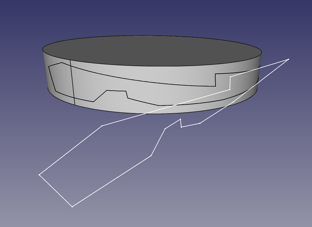
This is a plain sketch tangent to a cylinder, with a random polygon inside:
The script rolls the sketch along the cylinder surface. Only straight lines at the moment.
Text sticker:
Equal to the previous one but with strings. The font must must be made only of straight lines.
It works for any face orientation (but not character length, this will be improved )
Text Sticker Code:
"""
Javier Martinez Garcia 2015 GPL
"Text sticker" script
"""import Draft
from math import sin, cos, pi
BaseCylinder = Gui.Selection.getSelectionEx()[0].SubObjects[0]
# Cylinder axis:for edge in BaseCylinder.Edges:
ifstr(edge.Curve)[0] =="C":
AxisPoint = edge.Curve.Center
AxisDirection = edge.Curve.Axis
CylinderRadius = edge.Curve.Radius
break# For text string:
FaceList = []
SelStrings = Gui.Selection.getSelection()[1].Shape.Wires
wire0 = SelStrings[0]
p1 = wire0.Edges[0].Curve.StartPoint
p2 = wire0.Edges[0].Curve.EndPoint
p3 = wire0.Edges[1].Curve.EndPoint
va = p1 - p2
vb = p3 - p2
SketchNormal = ( va.cross( vb ) ).normalize()
TangencyPoint = AxisPoint + SketchNormal*CylinderRadius
CylRevPlane = ( SketchNormal.cross( AxisDirection ) ).normalize() # perpendicularfor wire in SelStrings:
defH( n, m ):
#Hamilton product
w = n[0]*m[0] - n[1]*m[1] - n[2]*m[2] - n[3]*m[3]
i = n[0]*m[1] + n[1]*m[0] + n[2]*m[3] - n[3]*m[2]
j = n[0]*m[2] - n[1]*m[3] + n[2]*m[0] + n[3]*m[1]
k = n[0]*m[3] + n[1]*m[2] - n[2]*m[1] + n[3]*m[0]
return ( w, i, j, k )
defRotateVector( V, Axis, alpha ):
#Rotate 3d vector with axis and angle using quaternions
csa2 = cos( alpha /2.0 )
ssa2 = sin( alpha /2.0 )
R = ( csa2, ssa2*Axis[0], ssa2*Axis[1], ssa2*Axis[2] )
RT = ( csa2, -ssa2*Axis[0], -ssa2*Axis[1], -ssa2*Axis[2] )
V = ( 0, V[0], V[1], V[2] )
RV = H( H( R, V ), RT )
return ( RV[1], RV[2], RV[3] )
#projectpointocylinderdefpoint2Cyl(p):
# input p = FreeCAD.Vector( x, y, z )
L0 = FreeCAD.Vector(p)
L1 = FreeCAD.Vector(p)
E_TGL_P0A = L0.projectToPlane( TangencyPoint, CylRevPlane )
E_TGL_P0B = L1.projectToPlane( TangencyPoint, CylRevPlane ).projectToPlane( AxisPoint, SketchNormal )
VBA = E_TGL_P0A - E_TGL_P0B
VBA_N = (E_TGL_P0A - E_TGL_P0B ).normalize()
ARC_RAD = ( p - E_TGL_P0A ).Length / CylinderRadius
# Turn direction
Aux_VRotA = FreeCAD.Vector( RotateVector( VBA_N, AxisDirection, ARC_RAD ) )
Aux_VRotB = FreeCAD.Vector( RotateVector( VBA_N, AxisDirection*-1, ARC_RAD ) )
if (Aux_VRotA - p ).Length > ( Aux_VRotB - p ).Length:
VRot = Aux_VRotB
else:
VRot = Aux_VRotA
RP0 = FreeCAD.Vector(VRot).multiply( CylinderRadius ) + E_TGL_P0B
return RP0
WireBS = []
for edge in wire.Edges:
points = []
for i inrange(100):
p = edge.valueAt( edge.Length*i /100.0 )
rp = point2Cyl(p)
points.append( rp )
rp = point2Cyl( edge.Curve.EndPoint )
points.append( rp )
SPL = Part.BSplineCurve()
SPL.interpolate( points )
SPL = SPL.toShape()
WireBS.append( SPL )
Face = Part.makeFilledFace( WireBS )
FaceList.append( Face )
Compound = Part.Compound( FaceList )
Part.show( Compound )
To use it, create a cylinder, place a string tangent to it; select the cylindrical surface and the text; run the script. Is very important that the font type of the text is made from straight lines, otherwise it will fail. The font I've used for testing is "UASquare".
Next step is to get it to work with circular edges.
UPDATE 1
The script for sketches is almost working, some screenshots:
Top view of the generated frame:
Generated frame:
This is the step that I'm trying to automatize:
Create faces from edges, create shell from faces, create solid from shell.
Imagine that you draw a house or a building in FreeCAD with all its details and interior elements. Wouldn't it be awesome if you could get into just like if you were walking inside?
This "tour camera" macro makes it possible.
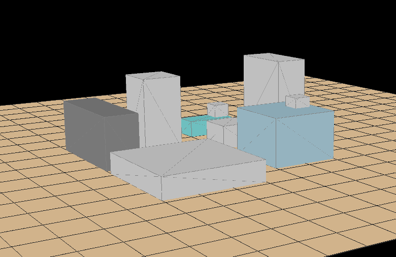
This is the small "town" I've created for testing this macro. Download it here, get the full macro
code at the bottom of the post, and follow this microtutorial
(notice the camera track in orange)
How does it work?
Very simple, create a sketch over the surface you want to travel and exit. Then, switch view mode to "perspective view", and finally, at the previous sketch, select one line and paste this at the python console:
-Gets camera node and sketch track as a list of edges
-Iterates over the list of edges, positioning the camera from edge start to the edge length position, looking at the edge endpoint.
If you did the above, you should be travelling like this:
But is not only your screen the one that shakes badly when you go from one line to the next, mine too.
When camera jumps from one line to the next, it is orientated to the new endpoint in one step. That's the origin of the shaking behavior.
So, with a bit more of complication, I've improved this (new "town" included :):
In this version, camera walks along the actual edge pointing its view to a vector, with a given length and the same direction than the movement. Once this vector reaches the intersection with the next line, the camera rotates to align with the end point of that line.
In conclusion, you get a smooth transition and a nice walk around.
But that's the behavior roughly speaking, for the real thing, please look the code below.
# JMG November 2014from pivy import coin
import time
from FreeCAD import Base
camera = FreeCADGui.ActiveDocument.ActiveView.getCameraNode()
trajectory = Gui.Selection.getSelectionEx()[0].Object.Shape.Edges
camHeight =10# Height of the camera above the track
lookVectorLength =80# Distance from next line start where the camera starts to align with new directionfor i inrange( len( trajectory ) -1):
currEdge = trajectory[i]
currEdgeDir = ( currEdge.valueAt( currEdge.Length ) - currEdge.valueAt( 0.0 ) ).normalize()
nextEdge = trajectory[i+1]
nextEdgeDir = ( nextEdge.valueAt( nextEdge.Length ) - nextEdge.valueAt( 0.0 ) ).normalize()
currPos = currEdge.valueAt( 0.0 )
while (currPos - currEdge.valueAt( 0.0 ) ).Length < currEdge.Length:
currPos = currPos + currEdgeDir
camera.position.setValue( currPos + Base.Vector( 0, 0, camHeight ) )
cameraLookVector = currEdgeDir*lookVectorLength
if (cameraLookVector + currPos - currEdge.valueAt(0.0) ).Length > currEdge.Length:
L = ( cameraLookVector + ( currPos - currEdge.valueAt( 0.0 ) ) ).Length - currEdge.Length
lookVector = nextEdgeDir*L + nextEdge.valueAt( 0.0 )
else:
lookVector = currEdge.valueAt( currEdge.Length )
camera.pointAt( coin.SbVec3f( lookVector[0], lookVector[1], lookVector[2] + camHeight ), coin.SbVec3f( 0, 0, 1 ) )
Gui.updateGui()
time.sleep( 0.004 )
It features two configurable parameters:
- camHeight: height of the camera above the track ( over z axis )
-lookVectorLength: distance from the endpoint of the current line at witch the camera starts to rotate to align with the next line. Try values, the more it approaches to 0, the more shake you get. But too big values will shake too!
Before leaving, a funny thing: instead of the sketch track, select the 3d model and paste the code.
Code update:
A complex track may involve booleans, and , as every time you operate with a shape their subelements get reorganized, the result is something like what .rpv got trying to tour inside a 3d printer. Curious as a background video in presentations, but not the expected behavior.
The solution is to rearrange the list of edges so next edge start begins at the current edge end. It is achieved this way:
SelectedEdge = Gui.Selection.getSelectionEx()[0].SubObjects[0]
RawTrajectory = Gui.Selection.getSelectionEx()[0].Object.Shape.Edges

# Edge rearrangement inside trajectory list
trajectory = []
trajectory.append( SelectedEdge )
currentEdge = SelectedEdge
for n in range( len( RawTrajectory ) ):
  for edge in RawTrajectory:
    if edge.valueAt(0.0) == currentEdge.valueAt( currentEdge.Length ):
      trajectory.append( edge )
      currentEdge = edge
      break
Full code:
Complete version featuring everything:
# JMG November2014
from pivy import coin
import time
from FreeCADimportBase
camera =FreeCADGui.ActiveDocument.ActiveView.getCameraNode()SelectedEdge=Gui.Selection.getSelectionEx()[0].SubObjects[0]
RawTrajectory=Gui.Selection.getSelectionEx()[0].Object.Shape.Edges
# Edge rearrangement inside trajectory list
trajectory =[]
trajectory.append( SelectedEdge )
currentEdge =SelectedEdge
for n in range( len( RawTrajectory ) ):
for edge inRawTrajectory:if edge.valueAt(0.0) == currentEdge.valueAt( currentEdge.Length ):
trajectory.append( edge )
currentEdge = edge
break
camHeight =10 # Heightof the camera above the track
lookVectorLength =80 # Distance from next line start where the camera starts to align with new direction
for i in range( len( trajectory ) -1):
currEdge = trajectory[i]
currEdgeDir = ( currEdge.valueAt( currEdge.Length ) - currEdge.valueAt( 0.0 ) ).normalize()
nextEdge = trajectory[i+1]
nextEdgeDir = ( nextEdge.valueAt( nextEdge.Length ) - nextEdge.valueAt( 0.0 ) ).normalize()
currPos = currEdge.valueAt( 0.0 )
while (currPos - currEdge.valueAt( 0.0 ) ).Length< currEdge.Length:
currPos = currPos + currEdgeDir
camera.position.setValue( currPos +Base.Vector( 0, 0, camHeight ) )
cameraLookVector = currEdgeDir*lookVectorLength
if (cameraLookVector + currPos - currEdge.valueAt(0.0) ).Length> currEdge.Length:L= ( cameraLookVector + ( currPos - currEdge.valueAt( 0.0 ) ) ).Length- currEdge.Length
lookVector = nextEdgeDir*L+ nextEdge.valueAt( 0.0 )
else:
lookVector = currEdge.valueAt( currEdge.Length )
camera.pointAt( coin.SbVec3f( lookVector[0], lookVector[1], lookVector[2] + camHeight ), coin.SbVec3f( 0, 0, 1 ) )
Gui.updateGui()
time.sleep( 0.004 )
Some time ago, when I was investigating about octrees and voxels to create a true CNC simulator, I played a bit with Coin3d, the scene graph render of FreeCAD.
Coin3d is coded in C++, but can be accesed with Python using Pivy.
While I didn't find anything specially useful, I realized that one could easily plot math equations like this:
...which have a nice look and permit you to take curious snapshots, for example:
The code is:
from pivy import coin
sg = FreeCADGui.ActiveDocument.ActiveView.getSceneGraph()
print sg
for s inrange(5):
for n inrange(-25,25):
for i inrange(-25,25):
col = coin.SoBaseColor()
col.rgb=(i*2,n*2,s*2)
trans = coin.SoTranslation()
# equation: z = f( i, n ) s is to plot at several heights
trans.translation.setValue([i*2.5,n*2.5,(i/2.0)**2+(n/2.0)**2+s*5])
cub = coin.SoSphere()
myCustomNode = coin.SoSeparator()
myCustomNode.addChild(col)
myCustomNode.addChild(trans)
myCustomNode.addChild(cub)
sg.addChild(myCustomNode)
Because of a project involving solar-thermal panels, at the beginning of this year, I realized that the way of obtaining how much shadow-per-year-percentage an object projects over another object was very inaccurate. So I attempted to create a sun-simulator, where you place the objects that are near to the place you want to study and then, run a script that draws shadows (with their grey color as a function of the % of shadow) over the place. That way, you can smartly place your solar collector.
I've not gone that further, I left the (short) development once I knew that something ~ similar existed for free. Don't reinvent the wheel.
But I want to show this, because maybe it helps you to go a step forward with your own project.
The code is posted here (there are comments explaining how to create "buildings" and "panels")
If you have pyqtgraph in your system, copy and paste the code in a python terminal and you should see something.
I've been playing today with the camera positions, with the remote idea of a video-game in mind.
Camera command (I haven't found this at pyqtgraph docs, but here) example:
Today I was wondering how could I monitor the temperatures of my computer automatically, using something that runs at startup without doing anything manually.
This is the result:
A terminal with transparent background that shows the temps.
Code:
The code to display sensor values and update them two times per second is:
while [ 1 ]; do sensors; # Outputs cpu and motherboard temps aticonfig --odgt; # Outputs my AMD GPU temps. sleep 0.5; # Delay for 0.5 seconds done
Save it somewhere as .sh and give execution permissions.
To run the code above (or any other you want) in a terminal:
I've set previously a new profile of gnome-terminal (called "cristal") that has transparent background and "Temperaturas" as window label.
Then, using the --profile option I set that profile for the new terminal.
The option --zoom=0.85 reduces the terminal size at 85% (genius)
The parameter --geometry is more interesting:
Columns x Lines + Xposition + Yposition
The position is given by your screen resolution. On my screen, the window is in the upper right corner when X = 1920 and Y=0
And finally, PATH is the absolute path to the code you want to execute.
To execute at startup, go to "startup applications", add a new application and where it says "command", paste the line that starts "gnome-terminal --profile......" customized to suit your particulad needs.
Save it and you are done.
FreeCAD 0.14 is taking too long to be released and, if when you try to compile it, everything is a non-sense and you end up feeling frustrated and stupid (as happens to me every time), you may like this:
Frustration solved: Hamish Assembly2 workbench here
To Use it: Copy-Paste at FreeCAD command line the code above and then: -Select a point of the object you want to move -Select a point of another object where you want the previous one to be placed -Call the function (write V2V() at command line and Enter)
And you're done!
With this you can save some time when placing objects without the assembly workbench.
The function PSheet has 6 inputs, 4 mandatory and 2 optional:
L = Length of the base rectangle
H = Heigth of the base rectangle
W = Width of the base rectangle
R = Hole radius
The optional parameters are hole type (circle by default) and "hole density" set as 1/5 by default.
To get the same as the above photo type after copy-paste:
PSheet(100, 100, 1, 4)
Yes, is slow to load. I will try to improve that, maybe doing a big sketch with all the holes, extruding them and substracting to the main plane.
Now everything is created with sketches. The speed has improved but not enougth to create big sheets. Almost all time is spent doing the recompute step, the last line of the script. I don't know how to speed up that :s
This is the graph of the needed time as a function of the sheet length (with heigth equal to length):
Just for curiosity and to see that if you want to create something bigger than an 800x800mm sheet, you will need more than 24 hours.
Honeycomb :
If you give enougth width to an hexagonal pattern you get a honeycomb like this one:
Honeycomb cores are very common in carboon-fiber structures.
This is the first release of the Work Features macro. It can do what is shown in the video plus few things more.
Is not finished and I have to update some functions, but to know how it works, the code is here.
How to use it:
(I don't know exactly why, but the last part of this section has the fonts messed up, sorry for that)
At the moment, you need to copy and paste the code at the FreeCAD python terminal every time you open a new document.
Yes, I know I need to improve this. Any help is appreciated. ;)
Once you do that, you need to move by command line (need to improve here too) and these are the options:
-OriginObjects This is executed automatically at copy-paste, generates Origin and folders
-WorkPoint:
-MiddPoint # Select one or more edges and will place the middpoint
-Center # Select one or more circular edges and will place centerpoint
-FaceCenter # Select one or more faces and will place a point at geometrical center
-WorkAxis:
-TwoPoints # Select two points and will place an axis across
-CylinderAxis # Select a cylindrical face and will place its axis
-WorkPlane:
-AxisandPoint # Select one axis and point and will place a plane containing both
-ThreePoints # Select three points and will place a plane with the points inside
-PlaneandPoint # Select one plane and point and will place a parallel plane at point
The workflow is:
Select the needed objects for reference and then type the command.
For example, one command could be:
WorkPoint.FaceCenter()
to create a point at the center of the selected face.
or
WorkPlane.ThreePoints()
to create a plane across three points.
And that's all!
Tell me your experience with the macro or any suggestions you have :)
After working a bit more in the work-points script I realized that is obligatory to have origin work-features, as origin of coordinates point, X, Y, Z axis, XY, XZ and YZ planes.
A screenshot to clarify:
The colors of the axis are to distinguish them, and the origin work-planes colors are different from the future user-created work-plane colors.
Everything is ordered in the tree-view by name and invisible by default:
I'm trying to figure how to use Github, I think I have posted the code here
To use it, with a part or new document opened, copy-paste the code, that's all.