Showing posts with label FreeCAD. Show all posts

Wednesday, 30 December 2015

NiCr


NiCr (read as 'nicrome') is the name of my CNC Hot Wire Foam Cutter, an OpenSource/OpenHardware project that I'm making public with this post.

The github repository: https://github.com/JMG1/NiCr


Description:

As the name says, the machine cuts shapes from foam blocks, being the original intention to cut wing cores for lamination and molding.

I've composed a little video about it:


I'm opening this project in exchange of all the good things that the OpenSource world has given to me (I like to think about it as 'from the OpenSource to the OpenSource').

Details:

The NiCr project can be divided in three parts: Machine, Arduino and FreeCAD


-Machine:

The machine is the physical thing, and is being designed to be built from easy to find, easy to work with materials, like extruded aluminium tubes and simple bolted joints, taking into account a low budget and the DIY factor (only cut/drill/bend operations).

It features two CoreXY frames, easy-to-find Nema17 motors, and a spring tensor for the wire. The design is also very scalable and can, possibly, be applied to other type of machines.

The design has taken place between FreeCAD and the real world:

FreeCAD pictures:

Detail of the Nema17 stepper, X axis slider and belt pulleys

Machine assembled inside FreeCAD
Real world pictures:

Frame size

Slider on the X axis

First version of the cut-wire tensor


-Arduino:

The machine movement is done with an Arduino Mega 2560 board and a Ramps shield, that, together with four stepper drivers (A4988), some limit switches and a power source form all the electronics.
The firmware is being developed specifically for this machine, you can see some of its parts in this links:


-FreeCAD:

The shapes are created using FreeCAD existing tools and converted later to .nicr (similar to GCode) in a custom workbench.

This workbench features a parametric machine, a shape-to-path algorithm, trajectory planning and simulation tools.

Some pictures of the workbench:

Workbench and parametric machine

Cut path simulation result for three wings with different precision settings

Workbench demo video:


The result of the shape-to-path algorithm is a .nicr file that contains instructions similar to GCode and with this comes a question:
Why I have not used the path workbench (in development) and the existing GCode standard?
 Because this machine produces 2.5D shapes (could do '2.75D' with the addition of a fifth axis, to be studied) and the movement is very different to the movement of a 3D printer or mill, and by using 4 axis, someone can be mistaken and use the code for the wrong machine.
Anyway, it is going to be a documented language so export-import tools can be created if needed.


Conclusion:

NiCr is in active development, at the moment I'm trying to achieve a basic stability and usability of the software before releasing (and some documentation too, maybe the hardest thing!).
Once I achieve that, the code and machine 3d parts will be uploaded to github (I have not decided the particular license yet) After a complete day of reading about licenses, I have chosen the GNU GPL.

I'll be updating this post with any news I have.
-> January 1, code uploaded to github: https://github.com/JMG1/NiCr


By the way, have a happy 2016!

Javier.


Thursday, 10 September 2015

FreeCAD: Intersection Between Shapes

Hi!

This is a small script that will find intersection volumes between the selected shapes, for example, given two cubes and a sphere, this is the result:


It gives some transparency to the original shapes and also displays intersection volume at the report view.

The code is:

# JMG 2015
object_list = []
for obj in FreeCAD.Gui.Selection.getSelectionEx():
  obj = obj.Object
  object_list.append( obj )

for n in range( len(object_list) ):
  object_A = object_list[n]
  for i in range( len(object_list) ):
    if i <= n:
      pass
    
    else:
      object_B = object_list[i]
      common = object_A.Shape.common( object_B.Shape )
      if common.Volume > 0.0:
        FreeCAD.Console.PrintMessage( '-Intersection- ' + object_A.Name + ' with ' + object_B.Name + '\n')
        FreeCAD.Console.PrintMessage( 'Common volume: ' + str( common.Volume ) + '\n' + '\n' )
        
        intersection_object = FreeCAD.ActiveDocument.addObject( 'Part::Feature', 'Intersection_Volume' )
        intersection_object.Shape = common
        intersection_object.ViewObject.ShapeColor = ( 1.0,0.0,0.0,1.0 )
        object_A.ViewObject.Transparency = 80
        object_B.ViewObject.Transparency = 80

Thursday, 6 August 2015

FreeCAD: Double Slider Mechanism Animation

Since few days ago, this blog is two years old, and, also, last month it crossed the 4000 views/month barrier.
I was thinking about a way of celebrating this events, and last night I saw a .gif image about a flat mechanism at which I could be staring the whole day:


I don't know its exact name, but "double slider mechanism" seems appropriate. It belongs to the family of flat, four bar linkage mechanisms, and, possibly, there is no real use for this one. But it moves very smoothly, with the outer end of the rotating arm drawing some kind of ellipse.


The kinematics of this one are not too difficult (none of the family of four bar linkage mechanism are), and for the animation I have solved it in an analytical way.

The code:


# Javier Martinez Garcia    August 2015   GPL V2.0

from PySide import QtCore
from math import sin, cos, radians

# retrieve the objects from the document
slider_x = FreeCAD.ActiveDocument.getObject("Pad003002")
slider_y = FreeCAD.ActiveDocument.getObject("Pad003001")
arm = FreeCAD.ActiveDocument.getObject("Pad002001")


# store initial placement (needed to restore initial position)
slider_x_placement = slider_x.Placement
slider_y_placement = slider_y.Placement
arm_placement = arm.Placement

# store object placements in a new variable
r_slider_x_pl = slider_x.Placement
r_slider_y_pl = slider_y.Placement
r_arm_pl = arm.Placement


def reset():
  # function to restore initial position of the objects
  slider_x.Placement = r_slider_x_pl
  slider_y.Placement = r_slider_y_pl
  arm.Placement = r_arm_pl


# In this mechanism, "i" represents the angle of the rod in degrees
i = 0

# update function calculates object position as f(i) and increases i
def update():
  global i
  alpha = radians( i )
  x = 150.0*cos( alpha )
  y = 150.0*sin( alpha )
  slider_x.Placement = FreeCAD.Placement( slider_x_placement.Base + FreeCAD.Vector( 150-x, 0, 0 ),
                                          slider_x_placement.Rotation )
  
  slider_y.Placement = FreeCAD.Placement( slider_y_placement.Base + FreeCAD.Vector( 0, y, 0 ),
                                          slider_y_placement.Rotation )
  
  arm.Placement = FreeCAD.Placement( arm_placement.Base + FreeCAD.Vector( 0, y, 0 ),
                                     FreeCAD.Rotation( FreeCAD.Vector( 0,0,1), i))
  # update the scene
  FreeCAD.Gui.updateGui()
  # increase mechanism input position
  i += 1


# create a timer object
timer = QtCore.QTimer()
# connect timer event to function "update"
timer.timeout.connect( update )
# start the timer to trigger "update" every 10 ms
timer.start( 10 )


Download the .fcstd model and animation script here, on github.


Have fun!

Saturday, 18 July 2015

FreeCAD: Drill macro

I am working on a project that has a lot of drill operations. Being an "assembly", it can get quite tedious to create an sketch or part cylinder, place it and then do a boolean cut to make the drill. To speed it up, I have written a short macro that drills existing holes into the selected shapes:


Selection:


Script:

"""
Drill Macro
JMG 2015 GPL

Select a set of circles and then the shapes that you want to drill
"""

#get user selection of edges
SelEdges = Gui.Selection.getSelectionEx()[0].SubObjects  

# get user selection for shapes
SelectedShapes = Gui.Selection.getSelectionEx() 

# create the faces that will be extruded to create the drill
cutFaces = []
for edge in SelEdges:
  cutFace = Part.Face(Part.Wire(edge)) # create face from edge
  cutFaces.append( cutFace ) 

# drill all selected shapes minus first one (selected edges)
for i in range(len(SelectedShapes)-1): 
  #retrieve object from selection list
  SelShape = SelectedShapes[i+1].Object 

  #create an empty part object in the document
  drilledShape=FreeCAD.ActiveDocument.addObject("Part::Feature",'Drilled'+SelShape.Name)
  drilledShape.Shape = SelShape.Shape
  #cut selected shape and assign shape to "drilledShape"
  for f in cutFaces:
    drilledShape.Shape=drilledShape.Shape.cut(f.extrude(f.normalAt(0,0)*1000000))
    drilledShape.Shape=drilledShape.Shape.cut(f.extrude(f.normalAt(0,0)*-1000000))
  
  #turn off visibility of the selected shape and set same color for the new object
  SelShape.ViewObject.Visibility = False
  drilledShape.ViewObject.ShapeColor = SelShape.ViewObject.ShapeColor

Output:


Also, if you want to drill something more complex, like a slot, a variation of the script can do it:

Selection:

Script:
"""
Drill Edges Macro
JMG 2015 GPL

Select a set of edges that form a closed wire and then the shapes
that you want to drill
"""

#get user selection of edges
SelEdges = Gui.Selection.getSelectionEx()[0].SubObjects  

# get user selection for shapes
SelectedShapes = Gui.Selection.getSelectionEx() 

# create the face that will be extruded to create the drill
cutFace = Part.Face(Part.Wire( SelEdges )) 

# drill all selected shapes minus first one (selected edges)
for i in range(len(SelectedShapes)-1): 
    #retrieve object from selection list
    SelShape = SelectedShapes[i+1].Object 
    
    #create an empty part object in the document
    drilledShape=FreeCAD.ActiveDocument.addObject("Part::Feature",'Drilled'+SelShape.Name)
    
    #cut selected shape and assign shape to "drilledShape"
    drilledShape.Shape=SelShape.Shape.cut(cutFace.extrude(cutFace.normalAt(0,0)*1000000))
    drilledShape.Shape=drilledShape.Shape.cut(cutFace.extrude(cutFace.normalAt(0,0)*-1000000))
    
    #turn off visibility of the selected shape and set same color for the new object
    SelShape.ViewObject.Visibility = False
    drilledShape.ViewObject.ShapeColor = SelShape.ViewObject.ShapeColor

Result:


I have them in a custom toolbar and they have helped me to do things faster.

Maybe it helps you too :)

Bye!

Monday, 13 July 2015

What's going on this summer?

Hello!

I write this brief post to explain, among other things, what is currently happening with the sheet metal workbench:

The workbench at the moment is at 30%: Document structure is almost done, simple unfold is working and there are tools, like this one, to create even more complex and powerful features.


Also, I talked about some crowdfounding campaign or paid development for this workbench: all it is stopped because I've found a powerful sponsor (to be revealed in a future).


Am I working at sheet metal?

No. I'm going to be studying from now until I finish my degree, somewhere around December. But this does not mean a complete shutoff, there are things and important works on the way.

For example, for  the "maker" community, I am developing a new machine that is being born by the end of this year (and is part of my degree project). An open source machine with stepper motors, completely designed with FreeCAD, that works using Arduino and Python and is not a 3D printer.


Also, I've been working in improvements at the "Exploded Assembly Animation workbench" and additions to the macro "WorkFeatures"


In conclusion, things are going to freeze a bit, but no project is going to disappear.


Have a nice summer!!


Javier.

Friday, 5 June 2015

FreeCAD: Sheet Metal Update 2

Some screenshots of the current state of the workbench:

My goal sheet metal part and what can be currently done with the workbench:


It took me less than 5 minutes to draw it (I cheated a bit and did not put any real measurements). It sums up the current capabilities.

The object in the tree view:


You can also see the two orange icons, the only ones by now: "base fold" and "fold on edge".

The properties of the main feature, the fold:


It seems not too different from Update 1, but there has been a lot of work under the hood. Topological naming is a headache (every time a shape is modified, freecad sorts its edges, faces and vertexes randomly), and for the unfold, currently I have two approaches, the one that is currently working, produces this:


The other method, when finished, will allow to unfold partially and set different bend radius and k factors for each fold.

Thought priority is to finish Fold part class and unfold methods, to take a rest from it I code other tools, for example, hem along edges:


Or tear drop fold (a simplified fold object):


Slowly, this is starting to feel mature enough to use it in for real world. Once I solve some key problems, I will launch the crowdfunding campaing.

Any comment is greatly appreciated!

Thursday, 14 May 2015

FreeCAD: Sheet Metal Update 1

After some time without touching FreeCAD, I have managed to go a bit further at the development of the sheet metal workbench. Although is not really a "workbench", but a set of scripts at the moment, most of the critical part is done: workflow, document structure, data tree...

A screenshot:


This video sums up the current possibilities:


Objects are totally parametric and unfold algorithm is easier then ever. Next things to do are folds created from sketches (almost completed), get the unfold algorithm to work correctly with the k factor and other bend methods, set up the workbench with icons, and a lot of small utilities like reliefs, slots, punching...


The idea for this workbench is to be open source, but in a special way, because once completed and tested, I will start some kind of "crowdfunding" campaign so I can get some economic feedback. Once a specified amount is reached, I will upload the complete code to GitHub and start to work at documentation and further integration with FreeCAD (if it is considered good enough by the main devs).

With this method I hope to prove that open source software and economic benefit are not antagonist concepts.

What do you think?

EDITED: The development of this workbench (including funding campaign) is stopped until the first release of the project NiCr.

Monday, 20 April 2015

FreeCAD: Sticker Sketch and Text

Sometimes you need to model a special part like a shift drum for a motorcycle gearbox or something more simple like putting text on your perfectly modelled cup of coffee. While the content of this post does not completely solve any of this problems, it shows an important step forward. I'm doing this because of its similarity with some parts of the sheet metal workbench core.

What it does is to roll around a cylindrical surface a sketch or a text string. Code at the end of the post.

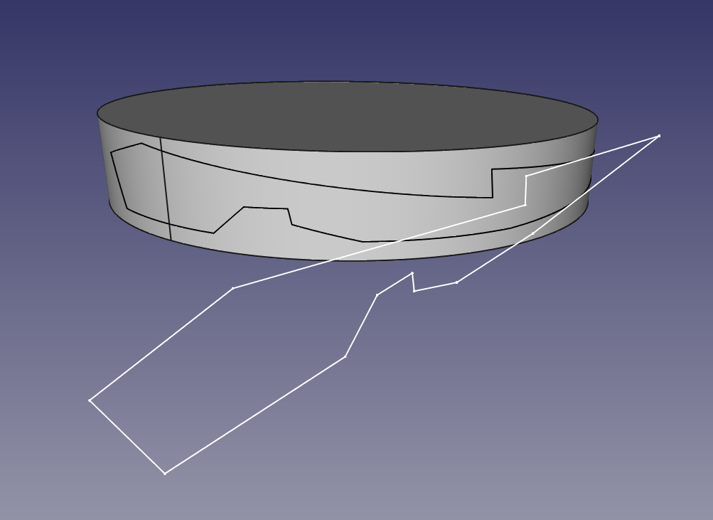
Sketch sticker:

This is a plain sketch tangent to a cylinder, with a random polygon inside:


The script rolls the sketch along the cylinder surface. Only straight lines at the moment.


Text sticker:

Equal to the previous one but with strings. The font must must be made only of straight lines.


It works for any face orientation (but not character length, this will be improved )


Text Sticker Code:


"""
Javier Martinez Garcia  2015  GPL
"Text sticker" script
"""

import Draft
from math import sin, cos, pi

BaseCylinder = Gui.Selection.getSelectionEx()[0].SubObjects[0]

# Cylinder axis:
for edge in BaseCylinder.Edges:
  if str(edge.Curve)[0] == "C":
    AxisPoint = edge.Curve.Center
    AxisDirection = edge.Curve.Axis
    CylinderRadius = edge.Curve.Radius
    break

# For text string:
FaceList = []
SelStrings = Gui.Selection.getSelection()[1].Shape.Wires
wire0 = SelStrings[0]
p1 = wire0.Edges[0].Curve.StartPoint
p2 = wire0.Edges[0].Curve.EndPoint
p3 = wire0.Edges[1].Curve.EndPoint
va = p1 - p2
vb = p3 - p2
SketchNormal = ( va.cross( vb ) ).normalize()
TangencyPoint = AxisPoint + SketchNormal*CylinderRadius
CylRevPlane = ( SketchNormal.cross( AxisDirection ) ).normalize() # perpendicular

for wire in SelStrings:
  def H( n, m ):
    #Hamilton product
    w = n[0]*m[0] - n[1]*m[1] - n[2]*m[2] - n[3]*m[3]
    i = n[0]*m[1] + n[1]*m[0] + n[2]*m[3] - n[3]*m[2]
    j = n[0]*m[2] - n[1]*m[3] + n[2]*m[0] + n[3]*m[1]
    k = n[0]*m[3] + n[1]*m[2] - n[2]*m[1] + n[3]*m[0]
    return ( w, i, j, k )

  def RotateVector( V, Axis, alpha ):
    #Rotate 3d vector with axis and angle using quaternions
    csa2 = cos( alpha / 2.0 )
    ssa2 = sin( alpha / 2.0 )
    R = ( csa2, ssa2*Axis[0], ssa2*Axis[1], ssa2*Axis[2] )
    RT = ( csa2, -ssa2*Axis[0], -ssa2*Axis[1], -ssa2*Axis[2] )
    V = ( 0, V[0], V[1], V[2] )
    RV = H( H( R, V ), RT )
    return ( RV[1], RV[2], RV[3] )

  #projectpointocylinder
  def point2Cyl(p):
    # input p = FreeCAD.Vector( x, y, z )
    L0 = FreeCAD.Vector(p)
    L1 = FreeCAD.Vector(p)
    E_TGL_P0A = L0.projectToPlane( TangencyPoint, CylRevPlane )
    E_TGL_P0B = L1.projectToPlane( TangencyPoint, CylRevPlane ).projectToPlane( AxisPoint, SketchNormal )
    VBA = E_TGL_P0A - E_TGL_P0B 
    VBA_N = (E_TGL_P0A - E_TGL_P0B  ).normalize()
    ARC_RAD = ( p - E_TGL_P0A ).Length / CylinderRadius
    # Turn direction
    Aux_VRotA = FreeCAD.Vector( RotateVector( VBA_N, AxisDirection, ARC_RAD ) )
    Aux_VRotB = FreeCAD.Vector( RotateVector( VBA_N, AxisDirection*-1, ARC_RAD ) )
    if (Aux_VRotA - p ).Length > ( Aux_VRotB - p ).Length:
      VRot =  Aux_VRotB

    else:
      VRot = Aux_VRotA

    RP0 = FreeCAD.Vector(VRot).multiply( CylinderRadius ) + E_TGL_P0B
    return RP0
  
  
  WireBS = []
  for edge in wire.Edges:
    points = []
    for i in range(100):
      p = edge.valueAt( edge.Length*i / 100.0 )
      rp = point2Cyl(p)
      points.append( rp )

    rp = point2Cyl( edge.Curve.EndPoint )
    points.append( rp )

    SPL = Part.BSplineCurve()
    SPL.interpolate( points )
    SPL = SPL.toShape()
    WireBS.append( SPL )
  
  Face = Part.makeFilledFace( WireBS )
  FaceList.append( Face )


Compound = Part.Compound( FaceList )
Part.show( Compound )


To use it,  create a cylinder, place a string tangent to it; select the cylindrical surface and the text; run the script. Is very important that the font type of the text is made from straight lines, otherwise it will fail. The font I've used for testing is "UASquare".

Next step is to get it to work with circular edges.

UPDATE 1


The script for sketches is almost working, some screenshots:


Top view of the generated frame:


Generated frame:


This is the step that I'm trying to automatize:


Create faces from edges, create shell from faces, create solid from shell.


Bye!!

Tuesday, 17 March 2015

FreeCAD: Shell Ecomarathon Prototype Cover

 ... or FreeCAD to the real world without 3d printing, but a 3 meters CNC mill:


Updated ( because we won!! :D )


Prototype Dátil 15 wins the European SEM on Ethanol


UPDATED: 


The result: 


On the news

 The story:

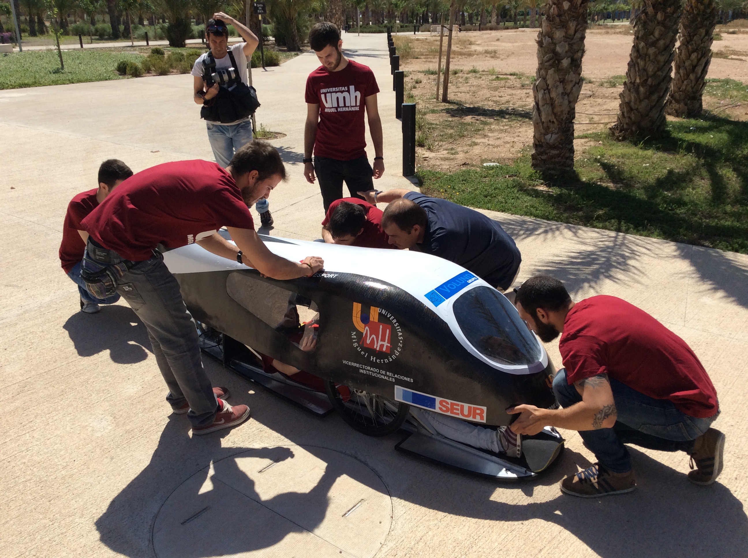
I am member of the UMH Team, a group of students that build a prototype car to race at the Shell Ecomarathon, an event that this year takes place at Rotterdam. Currently, we are in the first position of the spanish championship, leading it in the combustion category, with a fuel consumption of 1223 kilometers / litre of ethanol. In the European competition, we have been at the top ten, but past edition we finished 13th at combustion category and 3rd on ethanol.

This year we are building a completely new car that we hope bring us to the podium.


What I am showing here is the cover of the new prototype, that I designed using FreeCAD, simulated using SolidWorks, and later converted to CNC code using Hypermill. Special thanks go to Volund Group for their help and support.

The FreeCAD part:

The cover is designed using already existing tools, basically is a loft going through several sketches that I placed using a simple script.

This is the first one I did, just to test if FreeCAD was able to acomplish this work.


The car frame was made with Autodesk Inventor and imported as IGES, then I started to create the sketch-ribs and finally a loft through all them. I adjusted the sketches to obtain the desired shape. Once happy with it, I made the windows and a basic visibility test to ensure we are compliance with the rules of the race.

The rules specify that a pilot must be able to see a polar array of cylinders that are around the car with an angle of 30 degrees between each one.


Thanks to FreeCADs perspective view, I could check window sizes and do some optimization.

This is the pilot's point of view


Simulation:

The covering was simulated using SolidWorks, resulting in a Cx of 0.33.


Milling:

Once we performed another tests and confirmed that everything was ready, we started to machine a foam block to create a positive mould. We have used a medium-sized CNC milling center (Volund Group) that can handle the 3000 mm of length of this car:


Raw block:


Rough pass:


Smoothing pass:


The smoothing pass is finishing as I write this. What we are doing next is to epoxy and fiberglass it to create the negative mould and then, do the carboon fiber cover. I will edit this post to upload finished pictures.


I hope this serves an example of real world usage of FreeCAD, beyond 3D printing.

Maybe I do a tutorial to show how to model surfaces like this prototype cover, stay tuned. 

Bye!


Sunday, 21 December 2014

FreeCAD: Mechanical 3D scanner using Arduino

Scanning 3d objects mostly relies on several cameras and complex software, so it is not a low budget project. But I want to show you this quick idea I got to virtualize real models using scrap parts, Arduino and FreeCAD:


A 3 degrees of freedom arm that knows its position by the variable resistors that form its joints.
The arduino reads this resistors and prints the code by serial, where a python script running inside FreeCAD waits for the data.


I'm impressed with its accuracy because it recreates the real world objects with some kind of precision, in spite of being poorly built.

This photo is an example:


The propeller seen in the first picture:


With a better built arm, I'm sure this can improve enough to be usable.

Sunday, 14 December 2014

FreeCAD: Sheet metal idea part 2

UPDATE 2:  Document structure and basic tools
-
UPDATE: Ulrich has developed an unfolding algorithm that can be used as a macro.
-

Some things have changed since sheet metal part 1, where, for example, faces were classified by being flat or cylindrical, or folds only counted if their angle was 90º.

Even thought the algorithm is not finished (current problem is being discussed here), the new approach I'm going to explain here is more robust and is not even limited to face geometry or fold angles. You can even do folds with different radius, this face classifier can withstand it.

This is the part I'm going to use as example:


It has been created using this script, and you can download it here.

The workflow that I have in mind to unfold a part is:

- Select the face that will behave as base (all faces will be unfolded over the plane by it described )
- Run the script.

Let's start.

Import the libraries:

As always, we need to import some library. The only one we need is "Gui", from the  main FreeCAD library. In addition, we set the thickness of the sheet:

from FreeCAD import Gui
thk = 1.0

Retrieve user selection:

This is a basic command very useful at writing macros:

# Get Selected Shape and Face
SelObject = Gui.Selection.getSelection()[0].Shape
SelFace = Gui.Selection.getSelectionEx()[0].SubObjects[0]

SelObjects contains the selected shape and SelFace contains the selected face. Note that user only needs to click on the face and with that we can take the whole object.

Get ride off non useful faces:

The action starts here, but first: Which are the non-useful faces?
They are the ones marked in green at the picture:


This faces are not needed because they do not store useful geometry data. To clear things in a future, we are going to create a list excluding this faces:

faceList = [] # Create an empty list that will hold the filtered faces
for face in SelObject.Faces:
  apnd = True
  for edge in face.Edges: # Measure length of all edges from all faces
    if abs( edge.Length - thk ) < 0.001: #tolerance because float point things
      apnd = False # If edge length is equal to thickness, do not append it.
      break
  
  if apnd:  # If the face hasn't any edge with length == thickness, append it.
    faceList.append( face )


Did it work? Is something easy to test: select a face from the object and paste at FreeCAD's python console all the code.
Then, do:

len( SelObject.Faces )

len( faceList )


The first one gives "46" and the second "18". That's a great data reduction!

Unfold tree: step 1

We have a list containing only meaningful data, but this data is duplicated. Why? 


Is duplicated because the faces selected in the first picture (back of the part) are parallel to the faces on the second picture (top of the part). While is easy to create another filter to remove the repeated faces, is very hard to not lose the connection between faces with it.

So we are going to create a list containing wich face links to wich face or group of faces. This list has this form:

    index       A        B        C        D        E        F
     "list" =  [ [B],[A,C,D],[B],  [B,E,F], [D],    [D] ]

The index number belongs to the position in "faceList" of the face. The content under the index are the faces linked to that face.
To explain it better, "list" is the solution to faces links of this simplified part:


So how we create a list like that one?
Just run this little "monster":

# auxiliar function: find face number (index) in faceList:
def gfN( inFace ):
  SF_COM = inFace.CenterOfMass
  SF_NOR = inFace.normalAt( 0, 0 )
  for n in range( len( faceList ) ):
    F_COM = faceList[n].CenterOfMass
    F_NOR = faceList[n].normalAt(0,0)
    if SF_COM == F_COM and SF_NOR == F_NOR:
      break

  return n

# get selected face position (index)  in faceList:
SelFaceNumber = gfN( SelFace )

# auxiliar function: get faces linked to input face (returns position in faceList )
def gfR( inFaceN ):
  temporalList0 = []
  inFace = faceList[inFaceN]
  for inEdge in inFace.Edges:
    if str( inEdge.Curve )[1:5] == "Line":
      P_ia = inEdge.valueAt( 0.0 )
      P_ib = inEdge.valueAt( inEdge.Length )
      V_0 = ( P_ib - P_ia )
      for n in range( len( faceList ) ):
        if n != inFaceN:
          face = faceList[n]
          for edge in face.Edges:
            P_a = edge.valueAt( 0.0 )
            P_b = edge.valueAt( edge.Length )
            V1 = P_b - P_ib
            V2 = P_a - P_ia
            condition0 = abs( ( V_0.cross( V1 ) ).Length ) < 0.0001
            condition1 = abs( ( V_0.cross( V2 ) ).Length ) < 0.0001
            if condition0 and condition1:
              faceNumber = gfN( face )
              temporalList0.append( faceNumber )
              break

  # clean from repeated faces
  temporalList1 = []
  for i in temporalList0:
    if not( i in temporalList1 ):
      temporalList1.append( i )

  return temporalList1


compFaceRel = []
for fn in range( len( faceList ) ):
  data = gfR( fn )
  compFaceRel.append( data )


If you run the code above, and then type "comFaceRel" you should see something like:

[[3, 2], [4, 5], [0, 3, 6], [0, 7], [1, 8], [1, 4, 9], [2], [3, 10, 11], [4], [5, 12, 13], [7, 14], [7, 10, 15], [9, 13, 16], [9, 17], [10], [11], [12], [13]]

How a link is recognized:
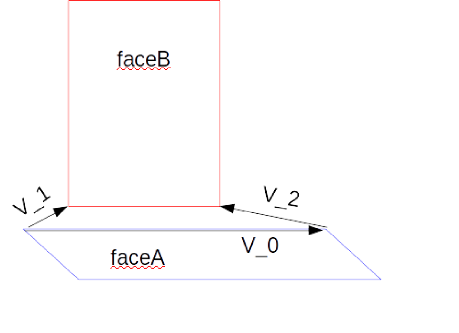


faceA is the current face being analyzed to inspect its links. FaceB is one of all the faces contained in facesList suspicious of being linked with faceA. 
V_0 the director vector of the current edge of faceA being inspected. V1 and V2 are vectors going from the end-points of the edge from faceA to the end-points of an edge owned by faceB. 
A face is linked if the cross products V1xV0 and V2xV0 have a length of 0.

All this is calculated inside the previous function "gfR".


At the moment, this is the current state of the sheet metal workbench. Next step is to get the link between final nodes of the tree of faces to the selected face to unfold. 
Taking the previous example model with faces A, B, C..., the needed list previous to unfold is, with B as unfold base:
                                                  [ [A,B], [C,D], [F,D,B], [E,D,B]]

Knowing that list would be the major step forward. With it, the unfold algorithm would be almost finished.


Complete code:

# JMG december 2014
from FreeCAD import Gui

thk = 1.0

# Get Selected Shape and Face
SelObject = Gui.Selection.getSelection()[0].Shape
SelFace = Gui.Selection.getSelectionEx()[0].SubObjects[0]

# remove faces placed on the thickness
faceList = [] # Create an empty list that will hold the filtered faces
for face in SelObject.Faces:
  apnd = True
  for edge in face.Edges: # Measure length of all edges from all faces
    if abs( edge.Length - thk ) < 0.001: #tolerance because float point things
      apnd = False # If edge length is equal to thickness, do not append it.
      break
  
  if apnd:  # If the face hasn't any edge with length == thickness, append it.
    faceList.append( face )


# auxiliar function: find face number (index) in faceList:
def gfN( inFace ):
  SF_COM = inFace.CenterOfMass
  SF_NOR = inFace.normalAt( 0, 0 )
  for n in range( len( faceList ) ):
    F_COM = faceList[n].CenterOfMass
    F_NOR = faceList[n].normalAt(0,0)
    if SF_COM == F_COM and SF_NOR == F_NOR:
      break

  return n

# get selected face position (index)  in faceList:
SelFaceNumber = gfN( SelFace )

# auxiliar function: get faces linked to input face (returns position in faceList )
def gfR( inFaceN ):
  temporalList0 = []
  inFace = faceList[inFaceN]
  for inEdge in inFace.Edges:
    if str( inEdge.Curve )[1:5] == "Line":
      P_ia = inEdge.valueAt( 0.0 )
      P_ib = inEdge.valueAt( inEdge.Length )
      V_0 = ( P_ib - P_ia )
      for n in range( len( faceList ) ):
        if n != inFaceN:
          face = faceList[n]
          for edge in face.Edges:
            P_a = edge.valueAt( 0.0 )
            P_b = edge.valueAt( edge.Length )
            V1 = P_b - P_ib
            V2 = P_a - P_ia
            condition0 = abs( ( V_0.cross( V1 ) ).Length ) < 0.0001
            condition1 = abs( ( V_0.cross( V2 ) ).Length ) < 0.0001
            if condition0 and condition1:
              faceNumber = gfN( face )
              temporalList0.append( faceNumber )
              break

  # clean from repeated faces
  temporalList1 = []
  for i in temporalList0:
    if not( i in temporalList1 ):
      temporalList1.append( i )

  return temporalList1


compFaceRel = []
for fn in range( len( faceList ) ):
  data = gfR( fn )
  compFaceRel.append( data )


Bye!