Sometimes you need to model a special part like a shift drum for a motorcycle gearbox or something more simple like putting text on your perfectly modelled cup of coffee. While the content of this post does not completely solve any of this problems, it shows an important step forward. I'm doing this because of its similarity with some parts of the sheet metal workbench core.
What it does is to roll around a cylindrical surface a sketch or a text string. Code at the end of the post.
Sketch sticker:
This is a plain sketch tangent to a cylinder, with a random polygon inside:
The script rolls the sketch along the cylinder surface. Only straight lines at the moment.

Text sticker:
Equal to the previous one but with strings. The font must must be made only of straight lines.

It works for any face orientation (but not character length, this will be improved )

Text Sticker Code:
"""
Javier Martinez Garcia  2015  GPL
"Text sticker" script
"""

import Draft
from math import sin, cos, pi

BaseCylinder = Gui.Selection.getSelectionEx()[0].SubObjects[0]

# Cylinder axis:
for edge in BaseCylinder.Edges:
  if str(edge.Curve)[0] == "C":
    AxisPoint = edge.Curve.Center
    AxisDirection = edge.Curve.Axis
    CylinderRadius = edge.Curve.Radius
    break

# For text string:
FaceList = []
SelStrings = Gui.Selection.getSelection()[1].Shape.Wires
wire0 = SelStrings[0]
p1 = wire0.Edges[0].Curve.StartPoint
p2 = wire0.Edges[0].Curve.EndPoint
p3 = wire0.Edges[1].Curve.EndPoint
va = p1 - p2
vb = p3 - p2
SketchNormal = ( va.cross( vb ) ).normalize()
TangencyPoint = AxisPoint + SketchNormal*CylinderRadius
CylRevPlane = ( SketchNormal.cross( AxisDirection ) ).normalize() # perpendicular

for wire in SelStrings:
  def H( n, m ):
    #Hamilton product
    w = n[0]*m[0] - n[1]*m[1] - n[2]*m[2] - n[3]*m[3]
    i = n[0]*m[1] + n[1]*m[0] + n[2]*m[3] - n[3]*m[2]
    j = n[0]*m[2] - n[1]*m[3] + n[2]*m[0] + n[3]*m[1]
    k = n[0]*m[3] + n[1]*m[2] - n[2]*m[1] + n[3]*m[0]
    return ( w, i, j, k )

  def RotateVector( V, Axis, alpha ):
    #Rotate 3d vector with axis and angle using quaternions
    csa2 = cos( alpha / 2.0 )
    ssa2 = sin( alpha / 2.0 )
    R = ( csa2, ssa2*Axis[0], ssa2*Axis[1], ssa2*Axis[2] )
    RT = ( csa2, -ssa2*Axis[0], -ssa2*Axis[1], -ssa2*Axis[2] )
    V = ( 0, V[0], V[1], V[2] )
    RV = H( H( R, V ), RT )
    return ( RV[1], RV[2], RV[3] )

  #projectpointocylinder
  def point2Cyl(p):
    # input p = FreeCAD.Vector( x, y, z )
    L0 = FreeCAD.Vector(p)
    L1 = FreeCAD.Vector(p)
    E_TGL_P0A = L0.projectToPlane( TangencyPoint, CylRevPlane )
    E_TGL_P0B = L1.projectToPlane( TangencyPoint, CylRevPlane ).projectToPlane( AxisPoint, SketchNormal )
    VBA = E_TGL_P0A - E_TGL_P0B
    VBA_N = (E_TGL_P0A - E_TGL_P0B  ).normalize()
    ARC_RAD = ( p - E_TGL_P0A ).Length / CylinderRadius
    # Turn direction
    Aux_VRotA = FreeCAD.Vector( RotateVector( VBA_N, AxisDirection, ARC_RAD ) )
    Aux_VRotB = FreeCAD.Vector( RotateVector( VBA_N, AxisDirection*-1, ARC_RAD ) )
    if (Aux_VRotA - p ).Length > ( Aux_VRotB - p ).Length:
      VRot =  Aux_VRotB

    else:
      VRot = Aux_VRotA

    RP0 = FreeCAD.Vector(VRot).multiply( CylinderRadius ) + E_TGL_P0B
    return RP0


  WireBS = []
  for edge in wire.Edges:
    points = []
    for i in range(100):
      p = edge.valueAt( edge.Length*i / 100.0 )
      rp = point2Cyl(p)
      points.append( rp )

    rp = point2Cyl( edge.Curve.EndPoint )
    points.append( rp )

    SPL = Part.BSplineCurve()
    SPL.interpolate( points )
    SPL = SPL.toShape()
    WireBS.append( SPL )

  Face = Part.makeFilledFace( WireBS )
  FaceList.append( Face )


Compound = Part.Compound( FaceList )
Part.show( Compound )
To use it, create a cylinder, place a string tangent to it; select the cylindrical surface and the text; run the script. Is very important that the font type of the text is made from straight lines, otherwise it will fail. The font I've used for testing is "UASquare".
Next step is to get it to work with circular edges.
UPDATE 1
The script for sketches is almost working, some screenshots:

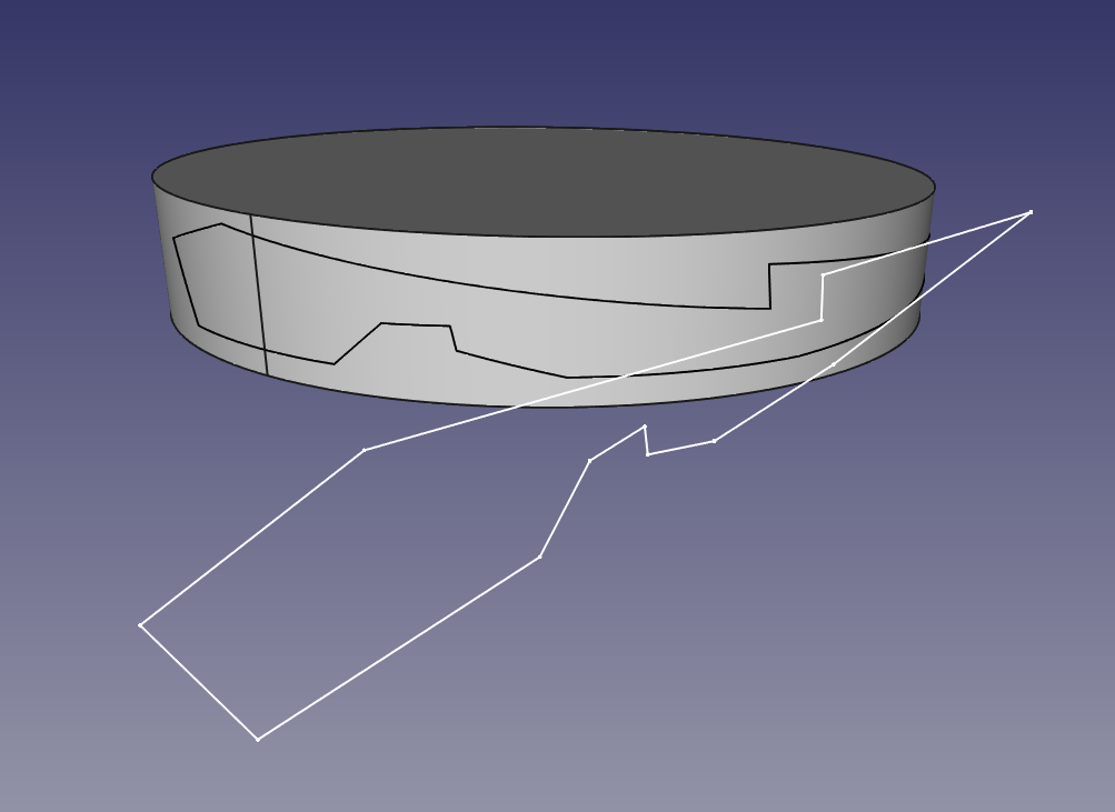
Top view of the generated frame:

Generated frame:

This is the step that I'm trying to automatize:

Create faces from edges, create shell from faces, create solid from shell.
Bye!!


