... this script creates a helix object and constantly adjust its pitch and height to create a compression-like effect.
As always, the function that calculates and commands the changes is called repetitively by a timer.
Video:
While the animation is running, you can change the values of pitch, length and compression by just typing in, for example:
Pitch = 3
Compression = 0.1 # Relative to the length of the "spring"
The code:
from __future__ import division
from PyQt4 import QtCore
import math as mt
import FreeCADGui
App.ActiveDocument.addObject("Part::Helix","Helix")
App.ActiveDocument.Helix.Pitch=5.00
App.ActiveDocument.Helix.Height=20.00
App.ActiveDocument.Helix.Radius=5.00
App.ActiveDocument.Helix.Angle=0.00
App.ActiveDocument.Helix.LocalCoord=0
App.ActiveDocument.Helix.Style=1
App.ActiveDocument.Helix.Label='Helix'
FreeCADGui.ActiveDocument.getObject("Helix").LineColor = (1.00,0.67,0.00)
i =0
Length =20
Pitch =5
Compression =0.5defSpring():
global i, Length, Pitch, Compression
i+=0.01
R = Pitch / Length
IH = Compression*Length*mt.cos(i)
P = Pitch + (R*IH)
App.ActiveDocument.Helix.Height = Length + IH
App.ActiveDocument.Helix.Pitch = P
if i ==1000:
i=0
timer = QtCore.QTimer()
timer.timeout.connect(Spring)
timer.start(5)
Before starting, I must warn that this is not intended to produce any realistic simulation.
I created it as a proof of concept and for fun.
How it works:
The milling script removes material by cutting the workpiece with the tool object (a rectangular box) in a simple Part.cut(tool) operation.
The tool object position is determined by taking the last point and the next point from the path points list. Then, the script creates vector and walks through it by steps. At every step, the tool cuts the workpiece, and every 4 steps, the document is refreshed. Refreshed means the command Part.show(workpiece). Because this command creates a shape every time is called, before Part.show(workpiece), the previous shape is removed.
Wild and dirty.
Below I try to explain how to use this script. You can get the full code here
Creating toolpath:
The first thing we need is the list of points that the "tool" will follow.
This list has the form:
Raw = Part.makeBox(raw_size[0],raw_size[1],raw_size[2])
Raw_shape = App.ActiveDocument.addObject("Part::Feature","Workpiece")
Raw_shape.Shape = Raw
Gui.ActiveDocument.getObject("Workpiece").Visibility=False
This is the function that performs the milling-like action:
L1 = Raw.cut(Tool_shape.Shape)
Part.show(L1)
i=0
n=0.0
swd =3# cut refreshing interval
s=0def Machining():global n, i,feed_rate, L1, Tool_radius, swd, s
if i <=len(Program):
Current_position = Tool_shape.Placement.Base
Vector_trajectory = App.Vector(Program[i+1])-App.Vector(Program[i])
Vector_direction =(App.Vector(Program[i+1])-App.Vector(Program[i])).normalize()
VT_modulus = Vector_trajectory.Length
VD_modulus =1.0if VT_modulus > VD_modulus*n*feed_rate:
Next_position = App.Vector(Program[i])+Vector_direction.multiply(n*feed_rate)+App.Vector(-Tool_radius,-Tool_radius)
n+=0.1else:
Next_Position = App.Vector(Program[i+1])
i+=1
n=0.0
s +=1if s > swd:
App.ActiveDocument.removeObject("Shape")
L1 = L1.removeSplitter()
Part.show(L1)
s =0
Tool_shape.Placement = App.Placement(Next_position, ToolR)
AnimatedTool.Placement = App.Placement(Next_position+App.Vector(Tool_radius,Tool_radius,0), App.Rotation(App.Vector(0,0,1),n*43))
L1 = L1.cut(Tool_shape.Shape)
Then, by calling repeatedly Machining() with a timer starts the animation:
timer=QtCore.QTimer()

timer.timeout.connect(Machining)

timer.start(1)
With the tool-path created above this is the result:
What's next?
Well, I've been playing with creating the points list using a script that follows the contour of a FreeCAD part. That way you will only need to execute that script and then run the simulation.
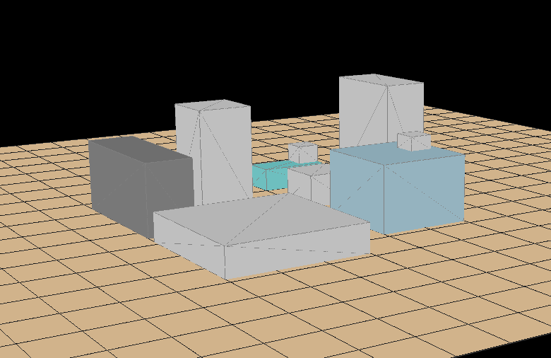
Because of a project involving solar-thermal panels, at the beginning of this year, I realized that the way of obtaining how much shadow-per-year-percentage an object projects over another object was very inaccurate. So I attempted to create a sun-simulator, where you place the objects that are near to the place you want to study and then, run a script that draws shadows (with their grey color as a function of the % of shadow) over the place. That way, you can smartly place your solar collector.
I've not gone that further, I left the (short) development once I knew that something ~ similar existed for free. Don't reinvent the wheel.
But I want to show this, because maybe it helps you to go a step forward with your own project.
The code is posted here (there are comments explaining how to create "buildings" and "panels")
If you have pyqtgraph in your system, copy and paste the code in a python terminal and you should see something.
I've been playing today with the camera positions, with the remote idea of a video-game in mind.
Camera command (I haven't found this at pyqtgraph docs, but here) example: